E4 Engineering · Harvey Mudd College · Jan → May 2024
Universal Antenna Remounting System
Davies Engineering Prize
Quick-swap antenna mounting for satellite and drone GPS tracking on a motorized telescope mount, engineered to ±0.1 mm positional accuracy with GD&T tolerancing.
I designed and prototyped the system in SolidWorks, engineered the radio-transparent CFRP joints and CNC-machined aluminum interfaces, and ran the project timeline with Gantt charts, daily stand-ups, and meeting minutes to hit on-time delivery.
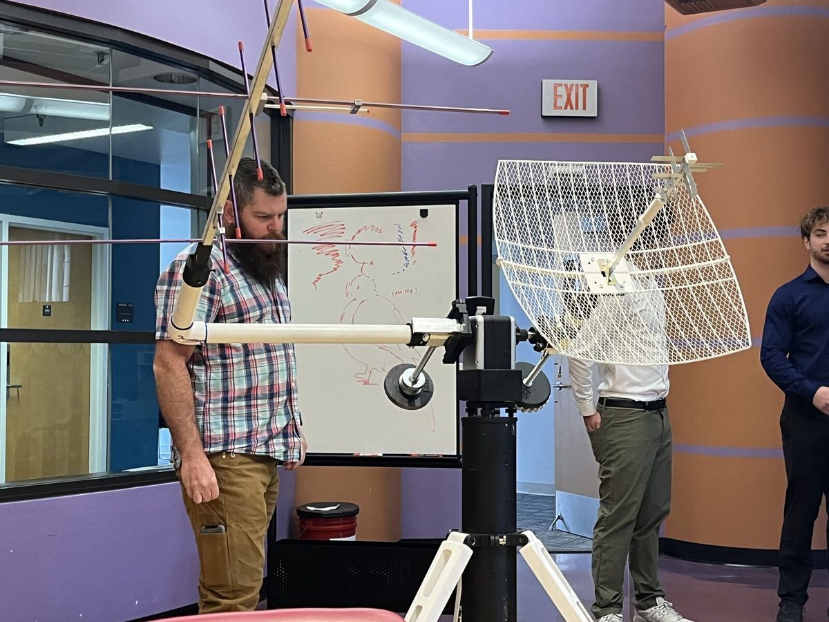
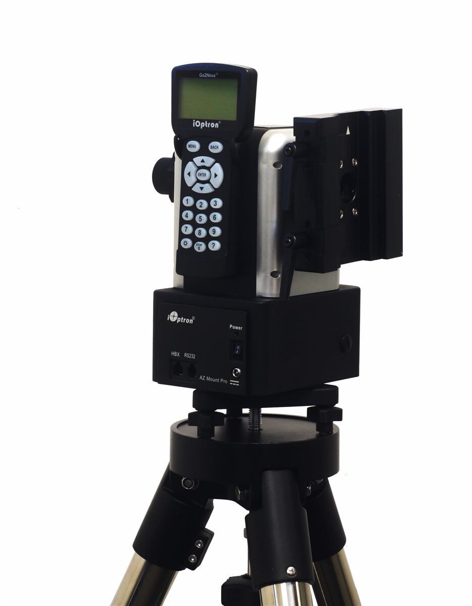
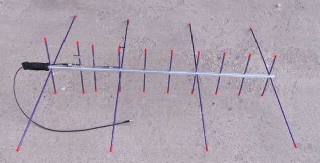
Our client needed to track satellites and drones with multiple antennas, a parabolic dish and arrow-style units, all driven by one motorized telescope mount (an iOptron AZ Mount Pro). Nothing on the market attached them. Existing options lacked modularity, precision, and field usability.
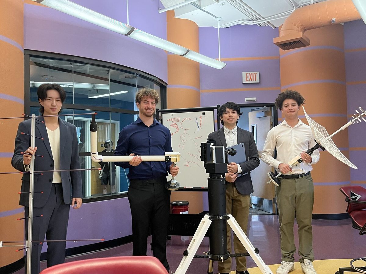
Our four-person E4 team delivered the Universal Antenna Remounting System: a modular attachment stack that swaps antennas in minutes while holding ±0.1 mm positional accuracy through GD&T tolerancing. The Engineering Department awarded the project the Davies Engineering Prize.
Problem & constraints
The client had no reliable way to mount antennas on the telescope, and the research happens in the field. Antennas have to swap in minutes without a machine shop, fit two antenna types today, and scale to whatever comes next.
- Sturdiness: survive handling, transport, and repeated field use
- Ease of attachment: full antenna swap within minutes
- Adaptability: modular interfaces that extend to future antennas
- Signal integrity: no interfering material inside the antenna read zone
Design
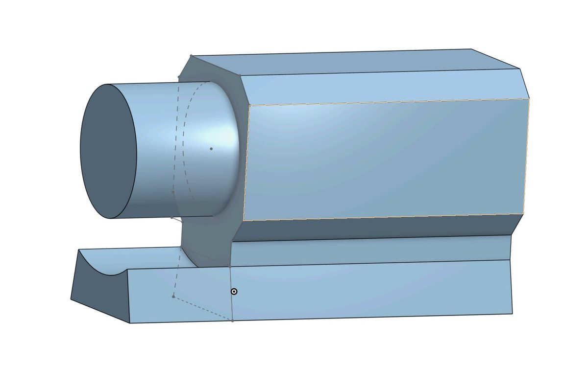
We sketched and iterated several geometries for modularity and balance, then modeled every component in SolidWorks. Material selection split the assembly into two regimes: radio-transparent CFRP, nylon, and PVC anywhere near the antenna read zone, and CNC-machined aluminum at the high-stress telescope interface.
We also wrote the evaluation plan up front instead of after the fact: structured test protocols with objective scoring for sturdiness, compactness, usability, and adaptability.
Fabrication
Each subsystem got the process its loads and RF constraints demanded:
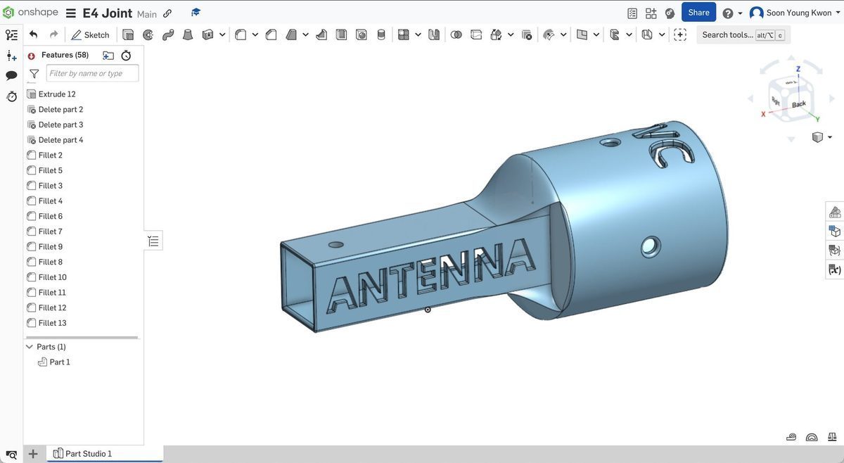
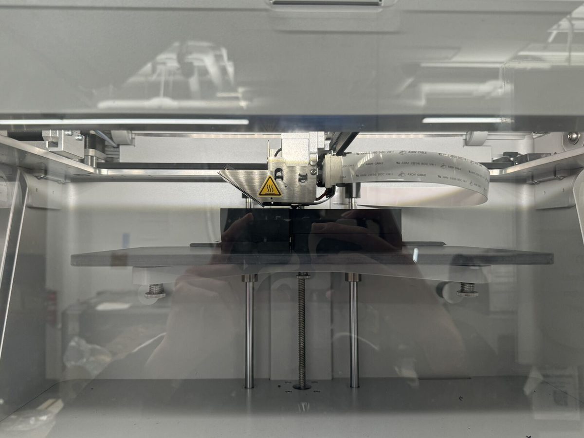
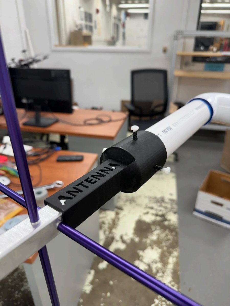
- Antenna-to-PVC joint: carbon-fiber 3D printed for strength at low weight, with nylon bolts for quick swaps and antenna rotation
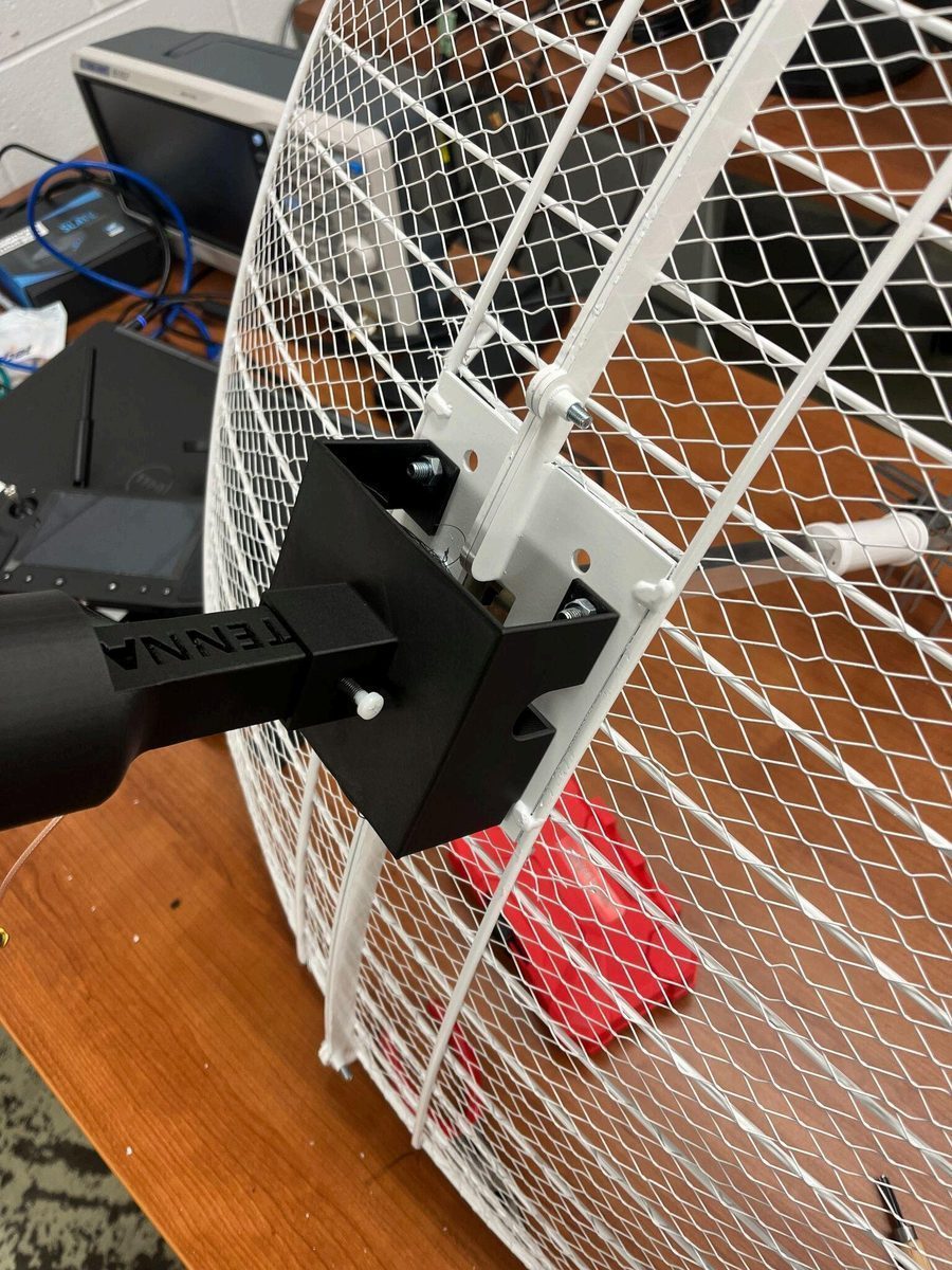
- Parabolic antenna attachment: CFRP-printed adapter panel, slim enough for compact storage, bolted for detachability
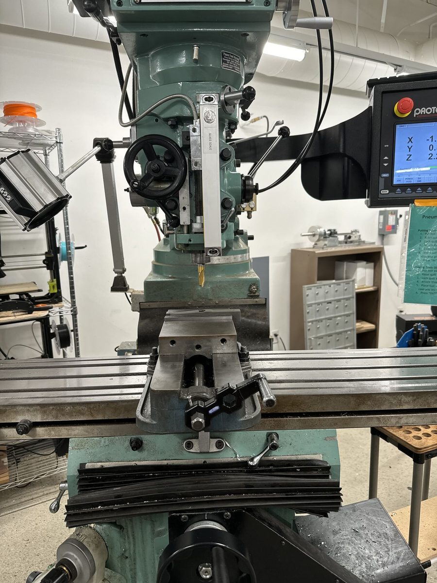
- Telescope mount piece and sleeve: CNC-machined aluminum with threaded rods, counterbalance support, and engraved branding
- PVC beam joint: chemically bonded elbow plus fasteners for structural stability
Testing & verification
Every prototype was scored against the design objectives with structured tests:
- Sturdiness: intended-use cycling, drop tests, and deflection measurements
- Compactness: measured volume and height against storage requirements
- Ease of use: timed attach and detach trials with E4 peers
- Signal integrity: verified no interfering materials in the antenna read zone
- Rotation: confirmed orientation adjustment for antenna polarization
- Adaptability: interview-based assessment of future antenna integration
Outcome
We delivered a field-ready modular mounting system. Antenna swaps take minutes, setup time dropped, and nothing in the load path gives up sturdiness or signal clarity. The interfaces are sized to accept future antennas, and the Engineering Department awarded the project the Davies Engineering Prize.
Lessons & next steps
This project put real hours into carbon-fiber 3D printing, CNC aluminum machining, designing to GD&T tolerances, and writing structured evaluation protocols for prototypes.
Given another iteration, I would refine the quick-release mechanisms and add automated alignment feedback to speed up field deployment.