
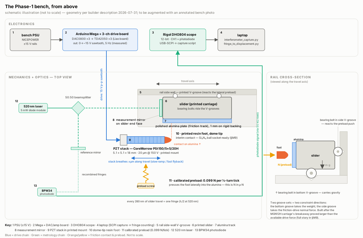
Everything in this project happens on one benchtop, where a drive chain turns a line of firmware into micrometers of ceramic motion, a friction contact turns those micrometers into unlimited travel, and a measurement chain reads the result in 260 nm increments. Chapters §M3 through §M11 each cover one box of Figure M2-2.
How a line of firmware becomes a step
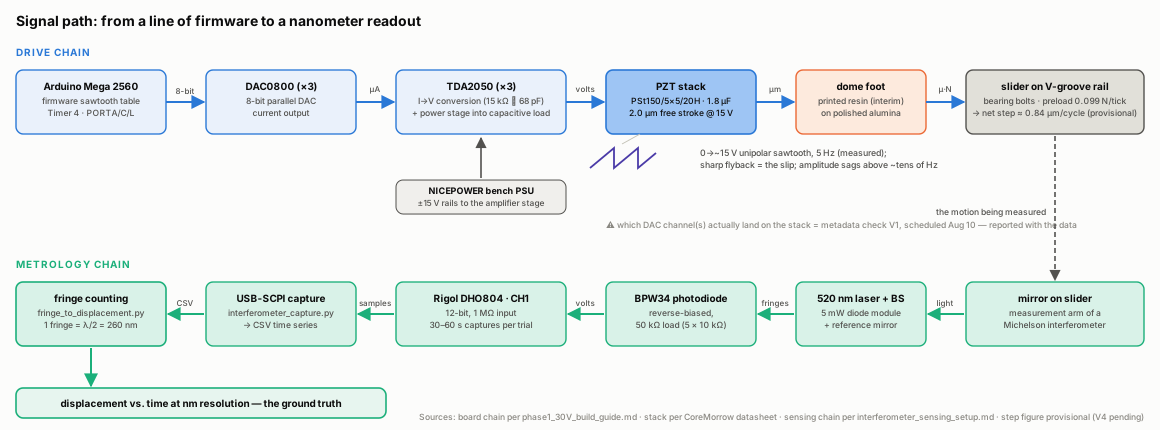
An Arduino Mega streams an 8-bit sawtooth table out of its parallel ports into a DAC0800 current-output DAC. A TDA2050 audio amplifier converts that current to voltage and then pushes a 0→~15 V sawtooth with a sharp flyback into a 1.8 µF piezoelectric stack [11, build guide]. The stack, an 18 mm CoreMorrow PSt150/5×5/20H, extends about 2 µm at that voltage (Derived: 20 µm × 15/150, from the datasheet-verified 20 µm at 150 V [9], scaled linearly, which is a rough assumption at a tenth of rated field).
A printed foot sits on the stack's nose and presses sideways into a polished alumina plate on the slider of a fully 3D-printed rail. The foot's tip is a 2 mm silicon-nitride ball (a bare resin dome, until August), and the pressing force comes from a spring I can set in calibrated 0.099 N clicks. During the slow ramp, friction drags the slider along, and during the fast flyback the slider's inertia wins and the foot slips underneath, so each cycle nets a step on the order of a micrometer.
When the interferometer is on the bench, a mirror on the slider's end face turns those steps into interference fringes, a BPW34 photodiode turns the fringes into a voltage, and the oscilloscope digitizes that voltage over USB for a Python script to count. That is the design, but as of this writing the measurement mirror is still on the old rig, so the travel numbers in this write-up were read with a ruler.
Spec box
| Item | Value | Source |
|---|---|---|
| Actuator | CoreMorrow PSt150/5×5/20H multilayer PZT stack | manufacturer datasheet, verified 2026-07-10 [9] |
| · stroke | 20 µm ±15% @ 0–150 V (≈2.0 µm at my 15 V, Derived, linear scaling) | [9] |
| · stiffness / blocking force | 60 N/µm ±10% / 1600 N | [9] |
| · size / mass / capacitance / resonance | 5.1×5.1×18 mm / 3.8 g / 1.8 µF ±20% / 50 kHz | [9] |
| Drive electronics | Liao open-source 3-channel board: Arduino Mega → DAC0800 ×3 → TDA2050 ×3 (corrected Gerbers, JLCPCB, self-populated) | [11]; §M6 |
| · measured output | ~15 V p-p unipolar (0→+15 V) sawtooth. 5 Hz bench default. Full amplitude only to ~tens of Hz into the stack's 1.8 µF (falls to ~3–5 V p-p by 200 Hz) | scope measurements 2026-07-13/17, project CLAUDE.md §2 |
| · measured at the stack | 14.7 V p-p at the stack's own wires, flyback ≈42 µs (commanded 60 µs). Derived 1.8 µF × 14.7 V ÷ 42 µs ≈ 0.63 A | scope, 2026-08-10 (run log) |
| · board cost | ~$50–80 in parts | [11] |
| Contact pair | 2 mm Si₃N₄ ball in a printed conical socket, on a polished 100×100×1 mm alumina plate (in service since mid-August 2026). A bare resin dome tip was the interim contact through the first half of August. It wore out within sessions | design_notes §16; run logs 2026-08-11, 08-20 |
| Preload | spring + screw, calibrated 0.099 N per ⅛-turn tick. Paper-strip procedure defines N = 0 | design_notes §18 |
| Linear guide | custom printed rail: bearing bolts riding printed V-grooves on bottom (gravity) and side (preload reaction). Replaced an MGN12H carriage whose breakaway exceeded the available drive force | builder, 2026-07-31; §M9 |
| Metrology | Michelson interferometer: 520 nm 5 mW diode laser, 50:50 beamsplitter, mirror on slider. BPW34 photodiode, reverse-biased, 50 kΩ load (5×10 kΩ) | interferometer_sensing_setup.md; builder, 2026-07-31 |
| · resolution basis | 1 fringe = λ/2 = 260 nm of slider travel | Derived from λ = 520 nm |
| Oscilloscope | Rigol DHO804, 12-bit, 70 MHz, $449 | project CLAUDE.md §2 |
| Capture pipeline | DHO804 → USB-SCPI → interferometer_capture.py → fringe_to_displacement.py (selftest passed 2026-07-02) |
project files |
| Bench power | NICEPOWER bench PSU, two channels in series → ±15 V rails (model number not recorded at the time of writing) | builder, 2026-08-06 |
| Fabrication | Elegoo Mars 5 Ultra (MSLA resin) for precision parts. Bambu Lab A1 mini (FDM) for bodies and fixtures. No FDM for flexure hinges (fatigue) | project CLAUDE.md §2 |
| Whole-project budget | $1,500–2,000 envelope | research_context.md |
| First measured motion | 2.51 mm in 10 min at N ≈ 0 on 2026-07-30 ≈ 4.18 µm/s ≈ 0.84 µm/cycle at 5 Hz (Derived). Confirmed by direction reversal 2026-08-20: 3.09 mm in 11 min forward, 0.54 mm in 13 min with the sawtooth reversed (≈0.94 and ≈0.14 µm/cycle, Derived). Corroboration runs still to be added (§M11) | bench log 2026-07-30; run log 2026-08-20 |
Drive electronics
The Mega's firmware holds the sawtooth as a lookup table and clocks it out over its parallel ports (Timer 4 pacing PORTA/C/L) so that all three DAC channels can update at the same instant. The board is a three-channel design because the end goal is a three-legged robot running 120°-offset waveforms (§M1, [8]).
Each TDA2050, which is nominally an audio power amp, converts its DAC0800's output current to voltage (15 kΩ feedback with 68 pF compensation) and then drives the stack, which is a very capacitive load [11, build guide]. The rails come from a NICEPOWER bench supply at ±15 V.
The output amplitude is ~15 V peak-to-peak (unipolar 0→+15 V), but for weeks the project's own documents said "30 V p-p." That figure turned out to be the supply span, not the signal, and the scope settled it (measured 2026-07-17, corrections logged).
Into the stack's 1.8 µF, the amplifier holds a clean full-amplitude sawtooth only up to a few tens of hertz, and by 200 Hz the amplitude has dropped to about 3–5 V p-p (measured 2026-07-13). This is why the bench runs at 5 Hz, why the motion is invisible to the naked eye, and why the interferometer exists at all. The board's full story, including the defective published Gerbers and their correction, is in §M6, and the sawtooth troubleshooting is in §M7.
The stack is wired across two channel outputs ("15 volts across Ch1 and Ch2" is how my bench notes put it), and which channel plays which role has not been pinned down with the scope. What has been measured, on 2026-08-10, is the voltage at the stack's own wires, 14.7 V p-p, with a flyback of about 42 µs against a commanded 60 µs [run log 2026-08-10]. Step-size claims in §M11 use that measured voltage, not the commanded one.
The actuator and its foot
The stack is hundreds of thin PZT layers co-fired into an 18 mm column (the datasheet does not give the exact layer count). It converts charge into length by the inverse piezoelectric effect, ΔL = n·d₃₃·V in the ideal stack model [5].
Its datasheet numbers (20 µm at 150 V, 1600 N blocking force, 50 kHz resonance [9]) make it the strongest and the most fragile thing on the bench. It could hold a person's weight, though only across the 20 µm it can move, and it must never see tensile stress or a reversed overvoltage. The stack sits in a hole printed into the flexure body and is clamped there by a screw driven in against it, with no adhesive, so the stack stays removable [builder, 2026-08-06].
My part is the MSLA-printed resin foot on the stack's nose. Through July it ended in a bare resin dome tip, which keeps the contact patch small and predictable, and the same foot geometry carried a conical socket for a 2 mm silicon-nitride ball. The ball was bought because resin was expected to gall against alumina within minutes of sliding (design_notes §16), and it stayed in the drawer for the first-motion hunt, on the reasoning that each cycle only slides the foot a micrometer or two.
That reasoning was right per cycle and wrong in total, because the foot slips back across the plate on every flyback, so the rubbing accumulates even when the net step does not. A ten-minute run at 5 Hz is millimeters of sliding, not micrometers. In August the dome proved that design note right, since a fresh one ran twice, went dead within the same session, and two plate changes did not revive it (§M11).
In mid-August the ball went into its socket and has been the working contact since, and the lever flexure went into service the same week (§M9's postscript carries that story). Photographing the worn resin tips is still on the data list, because surface-pairing effects are one of the things the reviews never report [5, 6, 7].
Rail, preload, and the physics they serve
The rail is the reason the July 30 result exists. Version one was a commercial MGN12H miniature linear guide. Its breakaway friction was bigger than the entire drive force my contact could produce, which I only established after building a force budget (Derived, §M9, §M10).
Version two is fully printed, with bearing bolts on the slider riding printed V-grooves, one set in the rail bottom and one set in the side wall. The bottom grooves carry the slider's weight and the side grooves react the lateral preload that the actuator pushes into the slider. Both groove sets give rolling contact where the old carriage had sliding seals. Figure M2-1's inset shows the cross-section.
Preload, the N in the friction force µ·N that drives every step, comes from a spring-and-screw mechanism calibrated to 0.099 N per ⅛-turn tick (design_notes §18), with a paper-strip touch-off defining zero. That makes the most sensitive parameter in stick-slip physics a dial setting instead of a guess.
On July 30 the motion showed up at the bottom of the dial, with the foot barely touching, and so did every August run. This is also a clue about how low this rail's drag is, but the breakaway measurement itself is still on the to-do list (§M9).
Metrology
At 5 Hz, a perfectly working motor here moves a few micrometers per second, which no eye can see, and for about a month I effectively ran blind experiments without knowing it (§M10 tells that story). The fix is a Michelson interferometer built from hobby parts on the same baseplate: a 520 nm, 5 mW diode laser module, a 50:50 beamsplitter, a reference mirror, and a measurement mirror mounted on the slider itself so the beam reads travel-axis motion directly.
The recombined beams land on a BPW34 photodiode, reverse-biased into a 50 kΩ load made of five 10 kΩ resistors in series, because that is what the parts bin had. Every 260 nm of slider travel walks the pattern through one full fringe (λ/2 at 520 nm). The DHO804 digitizes the photodiode voltage, and two Python scripts (interferometer_capture.py, then fringe_to_displacement.py) turn scope samples into displacement versus time.
On 2026-07-06 the first fringes showed up as a bull's-eye pattern (wavefront-curvature mismatch from the diverging diode beam, usable anyway with the photodiode at the pattern center). A fingertip tap on the measurement mirror visibly modulates the scope trace, which was the end-to-end proof that the sensing chain works.
The alignment that produced those fringes was done on the old rig, and as of this writing the measurement mirror has not yet moved onto the new slider. August's diagnosis took the bench days the realignment was supposed to get, so every travel number in §M11 is a ruler-and-masking-tape measurement. The interferometer goes back to being the project's ground truth once the mirror is on the slider (§M8).
Everything else on the table
The Mars 5 Ultra (MSLA resin) handles anything precise: feet, coupons, and flexures. The Bambu A1 mini (FDM) handles anything structural: fixtures, mounts, the rail's larger prints. One firm internal rule is never to use FDM for flexure hinges, because layer adhesion under cyclic load will fail by fatigue cracking (project CLAUDE.md §2). Nothing in the motion path except the stack, the bearings, the alumina, and the fasteners is store-bought.
What the system leaves out, for now
Compared with §M1's ambitions, the gaps in this bench are deliberate. The July 30 run was on the bare stack, with no flexure amplification. The ~3.5× lever leg that §M9 writes up has been the hardware since August 11, which means the August 20 run was on a different machine from the July one, and the characterization that matters gets done on the lever.
There is one axis and one foot, not three legs. The bench runs at 5 Hz by choice, and full amplitude holds to a few tens of hertz before it starts to fall away, so speeds stay in µm/s for now. Why the amplitude collapses by 200 Hz is not yet pinned down, and §M7 has the test that would settle it. Each limitation is left for a planned later stage.
The July 30 motion spent three weeks as "provisional," until the August 20 run, with the sawtooth's ramp and flyback swapped, closed out the artifact explanations that only work in one direction (§M11). The system as drawn is already enough for Phase 1's goal, a measured speed-versus-preload curve for a printed, 15-volt stick-slip motor.
Still missing from this chapter
This chapter still needs an annotated bench photo (the drawn schematic stands in until then), the bench supply's model number, a close-up of the stack in its printed pocket, and the bearing-bolt count and type for the rail cross-section caption. They get added as they are recorded, and nothing here gets guessed.