
The gap between thinking machines and the physical world
AI is already better than most people at writing, math, and coding. But it still cannot fold laundry or hand someone a screwdriver. Hans Moravec pointed this out in 1988:
"It is comparatively easy to make computers exhibit adult level performance on intelligence tests or playing checkers, and difficult or impossible to give them the skills of a one-year-old when it comes to perception and mobility." [1]
That gap is basically why this project exists. The intelligence side is getting solved without me, and the body side is not. In 2023 there were 162 robots per 10,000 factory workers worldwide, more than double what it was seven years earlier (74 in 2016) [2]. But this figure (robot density) counts machines against employees, not against tasks, so it shows how thinly robots are spread through a workforce and says nothing about how much of the work they do.
Factories are the easiest place for a robot to work (structured and fenced off), while homes, hospitals, disaster sites, and the inside of the human body are barely touched. I think this disconnect between capable minds and incapable bodies is one of the biggest technological limits on quality of life right now.
Robotics is about the closest thing to an epitome of what a mechanical engineer gets to do, and as a rising mechanical-engineering student it made sense to spend my four months on the frontier that is both impressive and actually useful to human quality of life [builder, 2026-08-06]. This write-up documents the response I could build myself to that gap, which is an attempt to demonstrate and measure one kind of machine muscle, a 3D-printed, low-voltage stick-slip piezoelectric actuator.
Robots are limited by their muscles
Whatever a robot knows, it can only do what its actuators allow. Actuation is hard in a way computation is not, because it has to move real mass against forces and spend energy doing it, at a size and price the application can afford.
The problem gets much worse as robots get smaller. Electromagnetic motors, the default muscle of big robotics, scale down badly. When one is shrunk, the available torque collapses faster than the size does, so a centimeter-scale robot built around tiny gearmotors ends up slow, weak, and power-hungry. This is a big part of why the microrobotics field has moved to smart-material actuators instead [5, 7].
The field's own numbers show the cost of this bottleneck. The most complete survey of miniature piezoelectric robots to date covers 342 references. Typical operating voltages in it run 60–200 V, untethered machines are rare exceptions, and its main performance table does not contain a single power-consumption entry, because the field mostly does not report one [7]. The equivalent review of stick-slip actuators admits the same blind spot, with no energy-efficiency data anywhere across 184 references [6].
So the argument is that AI needs bodies, bodies need muscles, and the muscles small bodies need are the ones nobody has finished building, especially at voltages and fabrication methods a normal person can afford. That last part is where a home lab can matter.
A field guide to machine muscles
Figure 1 sketches the five families most relevant to small robots, and Figure 2 places them quantitatively, using the comparison data that Liang et al. (2020) assembled in their study of robotic actuators versus biological muscle [3]. For comparison, biological muscle itself sits near 40% strain, 0.35 MPa, 40 kJ/m³, and 40% efficiency [3, Table 1].
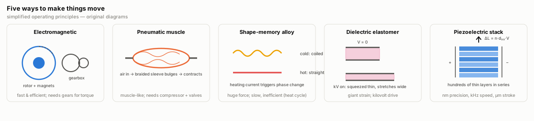
Electromagnetic motors and voice coils are mature technology, they run efficiently, and they cost little per watt. But a motor is a speed machine, so getting force takes a gearbox, which adds mass, backlash, compliance, and cost. Liang et al. put small electric motors around 0.1 kW/kg specific power, versus 1.6–2 kW/kg for hydraulics [3]. Below about 10 grams of robot, practical electromagnetic options mostly disappear.
Pneumatic artificial muscles of the McKibben type are the most muscle-like option, with about 25% strain at 1.16 MPa stress and efficiency around 49%. Liang et al. note that "the strain and stress of this PAM are slightly higher than those of biological muscle" [3, Table 1]. That holds for stress, but on strain it runs the other way against the muscle numbers in the same table, so I am quoting the authors' summary rather than endorsing it. The problem is everything attached to them, since compressors, valves, and tubing mean the robot is rarely self-contained.
When a shape-memory alloy (SMA) wire is heated, it changes crystal phase and pulls with "ultra-high stress to 200 MPa" [3]. Its work density of 10 MJ/m³ is the highest of any row in Liang's table. However, its theoretical efficiency is about 10%, and thermal time constants limit it to a few hertz. That combination makes SMA great for latches and one-shot mechanisms and hard to use for anything that has to move continuously.
Dielectric elastomers are soft capacitor sandwiches that squeeze flat and stretch wide under an electric field, with "giant strains of 380%" and efficiency reported at 60–80% [3]. The structural drawback is that the fields require kilovolt drive electronics, which are heavy, expensive, and unforgiving on a small platform.
Piezoelectric ceramics (PZT) deform when charged. The strain is tiny, around 0.1%, but stress, speed, and precision are in a different class from everything above. The manufacturer-verified datasheet for my own stack actuator, the CoreMorrow PSt150/5×5/20H, gives 20 µm of stroke (±15%) at 0–150 V from an 18 mm long device, which is 0.11% strain, with 1600 N of blocking force from a 5.1 × 5.1 mm cross-section. That works out to about 61 MPa of blocking stress (Derived: 1600 N ÷ 26 mm²), and the datasheet also lists 60 N/µm stiffness and a 50 kHz resonance [9].
However, the blocking force and the stiffness do not agree with each other. A 60 N/µm stack pushed through 20 µm of free stroke gives 1200 N, not 1600 N, and I am printing both as I have them. The stack's stored work per volume is ordinary, about 26 kJ/m³ (Derived: ½·k·x² over device volume, same datasheet numbers), and that figure rides on the stiffness, so it moves if the stiffness does.
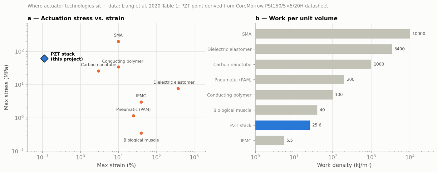
Figure 2. (a) Stress vs. strain for the actuator families in Liang et al. 2020, Table 1 [3]. The PZT-stack point is derived from my stack's datasheet [9]. Both axes are logarithmic. The technologies differ by orders of magnitude, which is why no single actuator wins everywhere. (b) Work per unit volume, same sources.
Why I chose piezoelectric
What made piezo worth four months is that it combines properties the other families cannot match all at once. It is solid-state, with no gears, coils, magnets, valves, or working fluid, just a block of ceramic and two wires, and nothing wears out except the surfaces deliberately chosen to rub together. Its resolution sits below a wavelength of light. Displacement is a smooth function of charge, and the stick-slip literature reports step resolutions of 2–40 nm [6]. Piezo scanners are what position atomic-force-microscope tips (general knowledge).
It is also fast, with ultrasonic piezo motors reaching 891 mm/s in linear form [5]. Even at 0.11% strain, a device cycling at just 1 kHz has a strain rate around 110%/s (Derived: strain × frequency), double biological muscle's 50%/s [3]. It delivers force without a transmission, and tens of MPa of actuation stress, orders of magnitude above muscle [3, 9], arrive directly and with zero backlash.
It self-locks at zero power (a friction-coupled piezo positioner holds position when switched off), and because the ceramic is a capacitor, holding a voltage draws no static current. For a battery-powered robot that spends most of its life standing still, this property matters a lot [6, 7]. It also scales down well. The physics works from 300-µm MEMS devices up to meter-scale optics mounts, and it is one of the few actuation principles that gets relatively better as everything shrinks [5, 7].
The costs are real too: roughly 0.1% strain, so the motion has to be converted somehow, 10–25% hysteresis in the voltage-displacement curve, creep under DC hold, ceramic brittleness, and a traditional 60–200 V drive requirement [5, 6, 7; research_context.md]. One comparative review sums the list up in one sentence: "the main challenges for piezoelectric artificial muscles include high stiffness, small strain, and relatively high operating voltage" [4]. Most of this project is an attempt to work around those challenges.
Camera autofocus rings, inkjet nozzles, diesel injectors, and scanning-microscope stages are all piezoelectric (familiar commercial examples, general knowledge). At the research frontier the same ceramics drive insect-scale flapping robots, robotic fish, and endoscopic tools inside the body [5, 7]. The pattern is that piezo wins wherever precision, speed, and compactness matter more than raw stroke.
Narrowing the bet to stick-slip actuators (SSPAs)
The central problem of piezo robotics is stroke conversion, which is turning 20 µm of ceramic expansion into centimeters of travel. The field has three broad answers: geometric amplification with flexure levers, resonance (ultrasonic motors, fast but demanding to machine and tune), and stepping, which accumulates unlimited travel out of micrometer-sized steps [5]. A flexure is a hinge with no pin in it, a thin section of solid material that bends where a bearing would otherwise pivot. Using one as a lever trades force for stroke by factors of 5–50×, though the stroke it gives stays finite.
Stick-slip is the simplest stepping scheme, and Figure 3 shows the cycle. The piezo is driven with a sawtooth, and during the slow ramp, static friction drags the slider along with the foot. At the cliff of the sawtooth, the foot snaps back in microseconds and the slider's inertia holds it in place while the foot slides underneath. One small step per cycle, repeated at frequency f, gives speed v = f × step. In every cycle, friction has to hold the slider to the foot during the ramp (µ·N > F_drag) and give way during the flyback (m·a_flyback > µ·N), and designing the device comes down to working between those two inequalities [first_motion_playbook.md; 6].
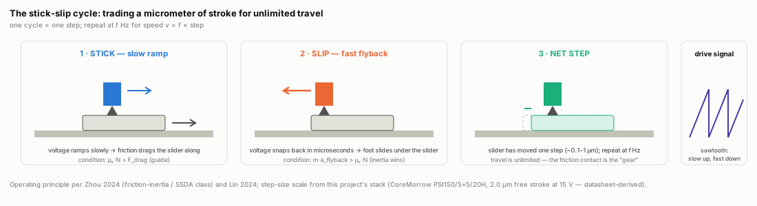
This scheme was chosen over the other two because every one of its advantages helps a home lab and a mobile robot at the same time:
- Of all the indirect piezo drives surveyed in Zhou 2024, stick-slip has the simplest mechanical structure, needing only a piezo element, a friction block, and a sawtooth [5, replication assessment in
paper_analyses/001], with no resonance tuning and no machined stator. - Travel is unlimited and the steps are sub-micron. Xing et al. measured 55 nm steps at 1 V, 96 nm at 2 V, and 187 nm at 4 V on a three-legged SSPA [8].
- The speed is adequate for locomotion in principle. Research SSPAs reach 12–46 mm/s [6], fast enough to walk a centimeter-scale robot across a desk. Whether a printed 15 V version gets anywhere near that is the open question, and G5 below says what would count.
The empty intersection
Reading the field's own review papers against each other turns up three blind spots. The first is that nobody has built a mobile stick-slip robot. Li et al.'s 342-reference survey of miniature piezoelectric robots contains zero demonstrated mobile stick-slip machines in its comprehensive performance table, and its two stick-slip entries are a stationary positioner and an incomplete row [7; extraction in paper_analyses/003].
Figure 4 plots that table, and the stick-slip region of the map is empty. The moment itself was not dramatic, since I was at home, just reading the paper, when I noticed the table had no mobile stick-slip robots in it at all [builder, 2026-08-06].
The nearest thing to an exception I know of is Adibnazari et al.'s tripedal microrobot [12], which the next blind spot raises for a different reason, and I have not yet confirmed from the paper itself whether it walks and whether it steps by stick-slip. Until I have, the claim I can defend is that Li's table holds no mobile stick-slip entry, not that no such machine exists.
The second blind spot is that nobody prints SSPAs. In Lin et al.'s 184-reference SSPA review, flexures are wire-EDM'd or CNC-machined metal almost everywhere. 3D printing appears exactly once (Adibnazari et al.'s tripedal microrobot [12]), and the review lists "no 3D-printed SSPAs" as an open gap [6].
Zhou 2024, covering the whole piezo-actuator field in 211 references, does not discuss additive manufacturing at all [5; noted in paper_analyses/001]. Where 3D printing does show up in piezo robotics, it is used only for the structural body, with commercial PZT bonded on [7, per paper_analyses/003], which is the architecture a home lab can build.
The third is that nobody goes low-voltage. Lin 2024 reports SSPA drive voltages of 80–400 V across the review, and lists designing specifically for under 30 V with multilayer stacks as an unexplored direction [6]. Li 2023 agrees from the robot side, where 60–200 V is typical, which is a big part of why so few of these machines carry their own batteries [7].
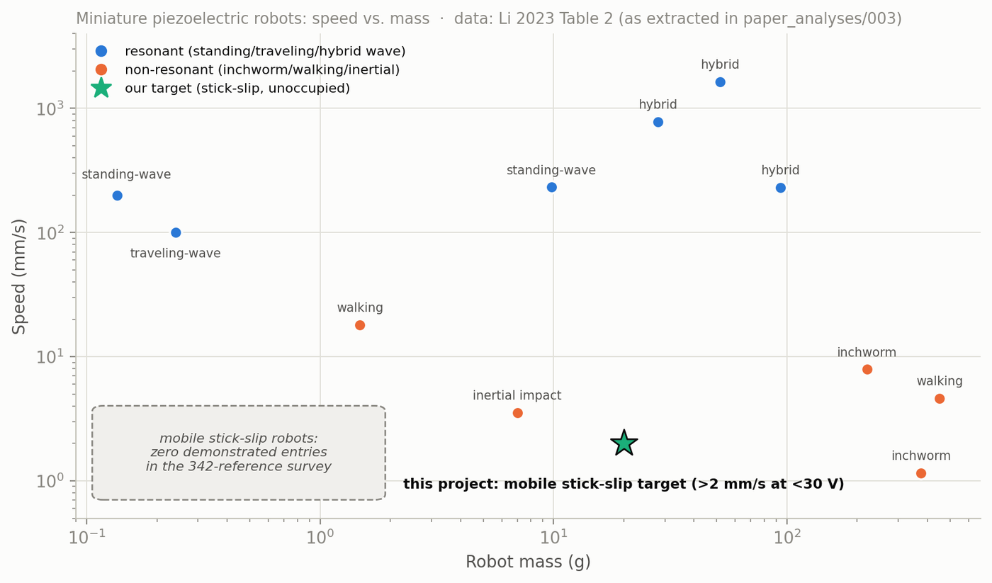
Figure 4. Speed vs. mass for the miniature piezoelectric robots in Li 2023's Table 2 (entries reporting both values; extraction in paper_analyses/003) [7]. Resonant machines (blue) own the fast frontier. Non-resonant steppers (orange) sit on the precise-but-slow shelf. The mobile stick-slip robot doesn't appear because none exists in the survey. The star is where this project aims.
SLA resin printing should pair well with SSPAs specifically, for four reasons, each checkable:
- The tolerances almost meet. Wire EDM holds sub-10 µm tolerances that hobby printers cannot match, but a calibrated MSLA printer holds roughly 25–50 µm, and the review-level assessment is that this is viable for proof-of-concept flexures that do not aim for nanometer resolution [6, assessment in
paper_analyses/002]. My own printed-fit testing (sla_tolerance_and_fits_guide.md) lands in the same range. - Iteration speed becomes the research method when the design space is this open. A flexure geometry costs about $2 of resin and prints overnight, where an EDM'd steel flexure means a quote from a vendor and a wait.
- Flexures, foot sockets, preload seats, and alignment features print as one monolithic piece, so there are no assembly tolerances stacking up across five machined components.
- The unknowns are themselves publishable. Polymer flexures raise questions metal never had to answer, among them viscoelastic creep, their contribution to hysteresis, and above all fatigue life. Nobody reports fatigue data in any of the three reviews [5, 6, 7; gap list in
benchmark_table.md]. A home lab that runs a printed flexure to 100,000 cycles and reports what breaks is contributing a number the field does not have.
The literature already provides stepping stones. Xing et al.'s three-legged SSPA showed that three triangular waveforms offset by 120° eliminate the backward-motion artifact completely, with 0% backslip at all tested frequencies, 580 µm/s at 900 Hz and 100 V, and 2 kg of vertical load capacity, using 3D-printed casing around commercial stacks [8]. Huang & Sun's 2019 lever-amplified stack, the closest same-class precedent to my hardware, demonstrated steps of 0.875 / 1.75 / 3.33 µm at 10 / 20 / 30 V [10], so steps of a useful size are still possible at the bottom of the voltage range.
Liao et al.'s open-source three-channel drive board (Arduino Mega, DAC0800s, TDA2050 amplifiers, roughly $50–80 in parts [11]) showed the electronics can be commodity-grade. Each of these stepping stones solves one piece, but nothing I have found assembles the pieces into a printed, low-voltage, mobile stick-slip machine, and that empty intersection is where this project aims.
The goals
The mission is to demonstrate and characterize the core motor of a 3D-printed, low-voltage stick-slip piezoelectric actuator, with every result, file, and failure published open-source. The constraints are four months (April–August 2026), a $1,500–2,000 total budget, fabrication limited to MSLA/FDM printing and hand assembly, and drive electronics limited to the ~15 V p-p my board actually delivers. Early project documents said "30 V." That figure turned out to be the power supply's span, not the signal, and the oscilloscope settled the amplitude [11; project CLAUDE.md §2].
The goals, in order, are:
- G1. First motion, measured. A working motor at my 5 Hz bench frequency moves a few micrometers per second, which no eye can see, so the readout is a home-built Michelson interferometer (520 nm laser, BPW34 photodiode, $449 oscilloscope) that resolves λ/2 ≈ 260 nm per fringe. Status. Achieved, and it took two tries. First travel came on 2026-07-30, with 2.51 mm of slider travel in 10 minutes at near-zero preload, which works out to ≈0.84 µm per cycle at 5 Hz (Derived), inside the predicted 0.5–1.0 µm band. It then would not reproduce for three weeks (§M10, §M11). On 2026-08-20 the motor ran 3.09 mm in 11 minutes forward and, with the sawtooth reversed, 0.54 mm in 13 minutes back [run log 2026-08-20]. Reversing on command rules out motion that is only drift, tilt, or vibration, so the result counts as confirmed. Two qualifications apply. The bench changed in between, since the silicon-nitride ball and the lever leg both went into service in that stretch (§M2, §M9), so August 20 shows motion on a revised machine rather than a repeat of the July run. Both travel figures were also read with a ruler against a masking-tape zero, not with the interferometer, because the measurement mirror is not yet on the new slider (§M2, §M8). First motion is demonstrated. It is not yet characterized, and the remaining corroboration runs are listed in §M11. On the first run, I sat at home watching the alumina plate creep away from the edge of a strip of masking tape I'd laid down as the zero mark, motion far too slow to watch in the moment, but over ten minutes the gap visibly grew [builder, 2026-08-06].
- G2. The curves. Speed vs. preload from 0 N up in 0.1 N steps, step size vs. drive voltage compared against the Huang & Sun ladder [10], repeatability spreads, and direction-reversal symmetry. These are the figures a future builder needs.
- G3. Metrology anyone can replicate. The interferometer plus capture pipeline (oscilloscope → Python fringe counter), documented well enough to rebuild from hobby parts and a mid-range scope (mine cost $449 [
CLAUDE.md§2], and the optics prices weren't recorded). The biggest lesson of this project so far is that I cannot debug what I cannot see. - G4. Report what nobody reports. Wear and galling on printed friction feet, and creep and fatigue of resin parts under cyclic load, are the metrics missing from all three reviews [5, 6, 7].
- G5. The path to a robot. Everything above is single-axis on a rail. The target the design points at, using Xing's topology [8] and my three drive channels [11], is a three-legged mobile platform above 2 mm/s, under 30 V, printable by anyone. That is Phase 2, and every Phase 1 measurement is chosen to feed it.
- G6. Open by default. Data, CAD, protocols, and write-ups released (OSF, GitHub, build logs), negative results included. If the motor had never moved, the metrology and the failure analysis were the publication. That standard does not change now that it has moved.
On to §M2 (the system at a glance)